
GGSY69320 Serial No. Write the serial number in the space above for future reference. Serial Number Decal (Under Seat) QUESTIONS? As a manufacturer, we are com- mitted to providing complete customer satisfaction. If you have questions, or if there are missing or damaged parts, we will guarantee complete satis- faction through direct assis.
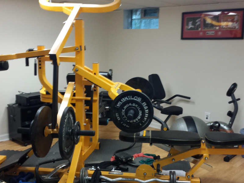
• Decal 1 GOLD'S GYM is a registered trademark of Gold's Gym International, Inc. Drivers Sony Vaio Pcg 5k2m Kamera Tersembunyi on this page. This product is manufactured and distributed under license from Gold's Gym Merchandising, Inc. Decal 1 Decal 2* Decal 2. • IMPORTANT PRECAUTIONS WARNING: To reduce the risk of serious injury, read the following important precautions before using the weight system. Read all instructions in this manual and in the accompanying literature before using the weight system. It is the responsibility of the owner to ensure that all users of the weight system are ade- quately informed of all precautions. • BEFORE YOU BEGIN Thank you for selecting the versatile GOLD’S GYM XRT 75 weight system.
ASSEMBLY & OPERATION MANUAL. This multi-gym by Inspire offers the key to unlocking your body’s potential. Regular strength training on a multi-gym has been.
The weight system offers a selection of weight stations designed to develop every major muscle group of the body. Whether your goal is to tone your body, build dramatic muscle size and strength, or improve your cardiovascular system, the weight system will help you to achieve the specific results you want. • ASSEMBLY Make Assembly Easier for Yourself Everything in this manual is designed to ensure that the weight system can be assem- bled successfully by anyone. Reaper Groove Templates. Before begin- ning assembly, make sure to read the information on this page.
This brief intro- duction will save you much more time than it takes to read it. • Frame Assembly Before beginning assembly, make sure you understand the information in the box on page 5. Locate and open the parts bags labeled “FRAME ASSEMBLY 1” and “FRAME ASSEM- BLY 2.” Press four 50mm Square Inner Caps (105) into the Rear Stabilizer (53) and the Long Base (120). Press two 25mm x 50mm Round Outer Caps (113) onto the bars on the VKR Upright (5).
Attach the VKR Upright (5) to the Long Base (120) with the two indicated M10 x 65mm Carriage Bolts (110) and two M10 Nylon Locknuts (87). Evan Moor Daily Word Problems Grade 4 Pdf here. Attach the Butterfly Upright (3) to the Short Base (2) with the two indicated M10 x 65mm Carriage Bolts (110) and two M10 Nylon Locknuts (87). Do not tighten the Locknuts yet. Attach the Seat Leg (9) to the Short Base (2) with the two indicated M10 x 65mm Carriage Bolts (110) and two M10 Nylon Locknuts (87). Press three 50mm x 75mm Inner Caps (58) into the Butterfly Top Frame (7). Attach the Butterfly Top Frame (7) to the Butterfly Upright (3) with two M10 x 95mm Bolts (92), two M10 Washers (91), and two M10 Nylon Locknuts (87). Attach the Left Weight Guides (64) to the Short Base (2) with an M10 x 155mm Bolt (95), two M10 Washers (91), and an M10 Nylon Locknut (87).
Slide two Weight Bumpers (49) onto the Left Weight Guides (64). Slide the Bottom Weight (1) onto the Guides. Attach the Left and Right VKR Arms (30, 31) to the VKR Upright (5) with two M10 x 75mm Bolts (101) and two M10 Nylon Locknuts (87). Press two 40mm x 50mm Inner Caps (21) into the Dip Assist Frame (127). Lubricate an M10 x 207mm Bolt (61) with grease. Press two 40mm x 50mm Inner Caps (21) into the Dip Assist Arm (128). Attach a Knee Rest Bumper (123) to the Dip Assist Arm with an M4 x 20mm Self-tapping Screw (14).
Attach the Dip Assist Arm (128) to the Dip Assist Frame (127) with two M10 x 65mm Bolts (18) and two M10 Nylon Locknuts (87). Attach the tethers on the two “L”-pins w/Tethers (60) to the Butterfly Frame (47) with an M4 x 20mm Self-tapping Screw (14). Lubricate an M10 x 80mm Button Head Bolt (104) and both sides of two Plastic Washers (56) with grease.
• Cable Assembly IMPORTANT: Refer to the CABLE DIAGRAMS on page 32 for help identifying the cables. Do not overtighten the bolts and nuts attach- ing the pulleys; the pulleys must be able to turn freely. Open the parts bag labeled “CABLE ASSEM- BLY.”. Wrap the Dip Cable (74) over a 90mm Pulley (78). Attach the Pulley to the Top Frame (6) with an M10 x 45mm Bolt (93) and an M10 Nylon Locknut (87). Wrap the Dip Cable (74) over a 90mm Pulley (78).
Wrap the Dip Cable (74) over a 90mm Pulley (78). Attach the Pulley to the second bracket on the right side of the Butterfly Top Frame (7) with an M10 x 45mm Bolt (93) and an M10 Nylon Locknut (87). Wrap the Squat Cable (73) over a 90mm Pulley (78). Attach the Pulley to the Top Frame (6) with an M10 x 45mm Bolt (93) and an M10 Nylon Locknut (87). Wrap the Squat Cable (73) under a 90mm Pulley (78). Wrap the Butterfly Cable (69) under a 90mm Pulley (78).
Attach the Pulley to the Double “U”- bracket (62) with an M10 x 45mm Bolt (93) and an M10 Nylon Locknut (87). Wrap the Butterfly Cable (69) over a “V”-pulley (55). Route the Leg Lever Cable (75) under a 115mm Pulley (119). Attach the Pulley and a Large Cable Trap (121) to the indicated side of the Butterfly Upright (3) with an M10 x 95mm Bolt (92), an M10 Washer (91), and an M10 Nylon Locknut (87). Wrap the Squat Low Cable (72) over a 90mm Pulley (78).